Turck 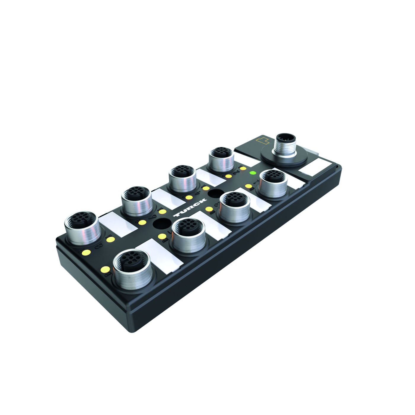
Turck
I/O Hub for Connection of Digital Signals to IO-Link Master 16 Universal Digital Channels, PNP
SKU: 100000881 Type: TBIL-M1-16DXP-B
Available 3–5 business days delivery
€206.80 / pieces
€246.09 incl. VAT
Features
- • IO-Link V1.1 Class B
- • Glass fiber reinforced housing
- • Shock and vibration tested
- • Fully potted module electronics
- • Protection classes IP65, IP67, IP69K
- • Galvanically isolated class B supply supports passive safety
- • ATEX Zone 2/22
- • CCC-Ex
- • 2 universal digital channels per slot
- • I&M data sets support installation and maintenance
- • IO-Link diagnostics for short circuit and supply voltage
General Information
| Mounting | 4 mounting holes, Ø 4.3 mm |
| MTTF | 79 years acc. to SN 29500 (Ed. 99) 20 °C |
| IO-Link | Green OFF Power off |
| IO-Link | Flashing IO-Link communication OK, |
| IO-Link | valid process data is being sent or received |
| IO-Link | Red ON IO-Link communication or module error |
| IO-Link | invalid process data or diagnosis enabled |
| Ambient temperature | from -40 to 70 °C |
| Dimensions (L x W x H) | 54 x 150 x 27.4 mm |
| Housing colour | Black |
| LED display | Color Status Description |
| Storage temperature | from -40 to 85 °C |
| Altitude | Max. 5000 m |
| Housing material | PA6-GF30 |
| Degree of protection (IP) | IP67 |
| Degree of protection (IP) | IP69K |
| Degree of protection (IP) | IP65 |
IO-Link
| Transmission rate | COM 2/38.4 kbps |
| IO-Link port type | Class A and Class B |
| Frame type | 2,6 |
| Connectivity IO-Link | 1 × M12 |
| IO-Link specification | V 1.1 |
Supply
| Sensor/actuator supply | Class A supply C0...C3 from V1 |
| Sensor/actuator supply | Short-circuit protected, 1.8 A per connector |
| Sensor/actuator supply | Class B supply C4...C7 from V2 |
| Admissible range | 18…30 VDC (UL rating 20.4…28.8 VDC) |
| Admissible range | V1: 4 A |
| Admissible range | V2: 4 A |
| Admissible range | V1+V2: max. 4 A up to 70 °C |
| Admissible range | V1+V2 max. 5.4 A up to 55 °C |
| Fault exclusion | Yes, acc. to EN ISO 13849-2, appendix D.2 |
| Electrical isolation | Potential isolation of V1 and V2 voltage group |
| Electrical isolation | Voltage proof up 500 VDC |
| Operating current | 120 mA |
| Supply voltage | 24 VDC |
| Connection technology power supply | M12 |
I/O LED Status
| Diagnostics | 2 Total - - - Undervoltage Undervoltage - - |
| Diagnostics | diagnostics V2 V1 |
| Diagnostics | 3 Vsens OC Vsens OC Vsens OC Vsens OC Vsens OC Vsens OC Vsens OC Vsens OC |
| Diagnostics | C7P1 C6P1 C5P1 C4P1 C3P1 C2P1 C1P1 C0P1 |
| Diagnostics | 4 DO7 SC DO6 SC DO5 SC DO4 SC DO3 SC DO2 SC DO1 SC DO0 SC |
| Diagnostics | 5 DO15 SC DO14 SC DO13 SC DO12 SC DO11 SC DO10 SC DO9 SC DO8 SC |
| INPUT | BYTE Bit 7 Bit 6 Bit 5 Bit 4 Bit 3 Bit 2 Bit 1 Bit 0 |
| Inputs | 0 DI7 C3P2 (B) DI6 C3P4 (A) DI5 C2P2 (B) DI4 C2P4 (A) DI3 C1P2 (B) DI2 C1P4 (A) DI1 C0P2 (B) DI0 C0P4 (A) |
| Inputs | 1 DI15 C7P2 DI14 C7P4 DI13 C6P2 DI12 C6P4 DI11 C5P2 (B)DI10 C5P4 DI9 C4P2 (B) DI8 C4P4 (A) |
| Inputs | (B) (A) (B) (A) (A) |
| Output | BYTE Bit 7 Bit 6 Bit 5 Bit 4 Bit 3 Bit 2 Bit 1 Bit 0 |
| C0…C7 0…15 | Green ON Input or output active |
| C0…C7 0…15 | Red ON Output active with overload/short circuit |
| C0…C7 0…15 | Flashing Power overload at the corresponding port. Both port LEDs are flashing. |
| C0…C7 0…15 | OFF Input or output inactive |
| Outputs | 0 DO7 C3P2 (B)DO6 C3P4 (A)DO5 C2P2 (B)DO4 C2P4 (A)DO3 C1P2 (B)DO2 C1P4 (A)DO1 C0P2 (B)DO0 C0P4 (A) |
| Outputs | 1 DO15 C7P2 DO14 C7P4 DO13 C6P2 DO12 C6P4 DO11 C5P2 DO10 C5P4 DO9 C4P2 (B)DO8 C4P4 (A) |
| Outputs | (B) (A) (B) (A) (B) (A) |
Digital inputs
| Number of channels | 16 |
| Low-level signal voltage | -3…5 VDC (EN 61131-2, type 1 and 3) |
| Max. input current | 15 mA |
| Type of input diagnostics | Channel diagnostics |
| High level signal voltage | 11…30 VDC (EN 61131-2, type 1 and 3) |
| Connectivity inputs | M12 |
Standard/Directive conformity
| Shock test | acc. to IEC 60068-2-27 |
| Approvals and certificates | CEUKCAATEX Zone 2/22 |
| Approvals and certificates | CCC-Ex |
| Approvals and certificates | Class I Div. 2 |
| Approvals and certificates | UV resistant acc. to DIN EN ISO 4892-2A (2013) |
| Vibration test | Acc. to IEC 60068-2-6 |
| UL Certificate | cULus LISTED 21 W2, Encl.type 1 IND.CONT.EQ. |
| Note on ATEX/IECEx | The Quick Start Guide with information on use in Ex |
| Note on ATEX/IECEx | areas must be observed. |
Digital outputs
| Electrical isolation | 500 VDC |
| Output type | PNP |
| Short circuit protection | yes |
| Type of load | Resistive, inductive, lamp load |
| Type of output diagnostics | Channel diagnostics |
| Output delay | 0.35 ms |
| Output connectivity | M12 |
Power supply
| Supply voltage | 24 VDC |