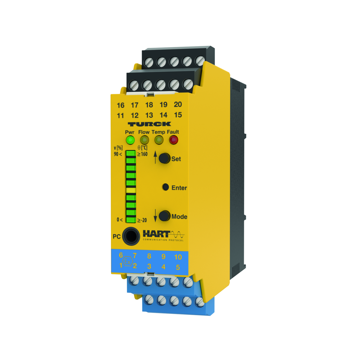
Processor Unit – For the Connection of FCS/FCI Product Series Ex Flow Sensors (NAEX) HART Device with Current and Transistor Outputs
Features
- • For Ex ia resp. Ex ib sensors
- • Analog output for flow
- • Transistor outputs for temperature and faults
- • Teaching upper and lower flow limit
- • LED band for indication of flow speed and media temperature
- • Monitoring of operating and display range
- • Detection of wire-break and short-circuit on the sensor side
- • Parametrized via pushbutton and FDT/DTM
- • Associated equipment [Ex ia Ga/Da]
- • Connection of flow probes Zone 0/20
Functional principle
All Ex FCS flow (immersion) and FCI (inline) sensors can be operated with the external processing unit FMX-IM. The flow module features four status LEDs as well as a 10-segment LED band for local monitoring. Software-based diagnostic options are also available to the user, such as wirebreak and short-circuit on the sensor side. Furthermore, monitoring of flow rates and media temperatures within a predefined operating and display range. The upper and lower limit are determined in relation to the analog output signal and implemented in the Teach mode. Working on the calorimetric principle, the connectible sensors not only detect the flow rate but also the media temperature. Parametrization is implemented either via pushbutton or software-supported via HART interface and then via the device specific IODD within the FDT frame PACTware or via SPDU.
Customizable output functions
| Error recognition | NAMUR error limits |
| Current range | 4…20 mA / 20…4 mA parametrizable |
| Display switch state | active high / active low parametrizable |
| Display switch state | (transistor output error monitoring only |
| Display switch state | active low) |
| Switching characteristic | PNP |
| Load | < 600 Ω |
| Error monitoring | transistor output |
| Characteristic | Output of probe signal, no linearization |
| Flow Monitoring | Analog output |
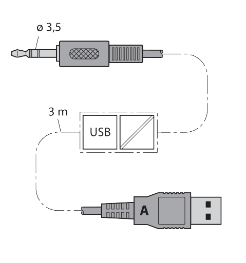
| Communication modes | Tool based engineering via DTM |
| Electrical connections | 5-pole removable reverse polarity protected terminal blocks |
| Type of fastening | screw connection |
| Temperature monitoring | transistor output |
| Switching current | 100 mA |
| Terminal cross-section | ≥ 1.5…≤ 2.5 mm² |
| Switching voltage | from 20 to 30 V |
LED display
| Flow | yellow on Active current output |
| Flow | flashing Teach mode / display of diagnostic data |
| Flow | for specification see manual |
| Temp | yellow off Switching output media temperature [low] |
| Temp | on Switching output media temperature [high] |
| Temp | flashing Teach mode / display of diagnostic data |
| Temp | for specification see manual |
| PWR | green on Operating voltage applied |
| PWR | Device ready for operation |
| PWR | flashing Operating voltage applied |
| PWR | HART communication active |
| LED | Color Status Description |
| Fault | Red Off Switching output fault [high] |
| Fault | On Switching output flow [low] |
| Fault | (for error pattern in combination with LEDs see manual) |
Tests/approvals
| Device designation | Ex II (1) G [Ex ia Ga] IIC resp. II (1) D [Ex |
| Device designation | ia Da] IIIC |
| Relative humidity | EN 60068-2-38 |
| Declaration of conformity EN ISO/IEC | 5108M |
| EC type examination certificate | TÜV 11 ATEX 078981 |
| Approvals | CE |
| Approvals | C-UL U.S. submitted |
| IECEx certificate of conformity | IECEx TUN 11.0005 |
| Electromagnetic compatibility (EMC) | Acc. to NE21 |
Mechanical data
| MTBF | 108 Years |
| Mounting method | DIN rail mounting and mounting panel |
| Ambient temperature | from -25 to 70 °C |
| Design | Signal processor |
| Housing material | Plastic, Polycarbonate/ABS |
| Degree of protection (IP) | IP20 |
| Abmessung | 89 x 110 x 27 mm |
Electrical data
| Measurement frequency | 5 Hz (every 200 ms with software filter) |
| Sensor current limitation | approx. 110 mA |
| Repeatability media temperature | typical ± 1 K |
| Medium temperature | [°C] with the SET button temporarily |
| Medium temperature | pressed |
| Measuring accuracy media temperature | typical ± 7 K |
| Sensor current | ≤ 70 mA |
| Sensor voltage | ≤ 7 VDC |
| No-load current I0 | ≤ 63 mA |
| Teach modes | Min/max adjustment. Teach modes incl. |
| Teach modes | DeltaFlow monitoring (teach modes are |
| Teach modes | automatically released with the change of |
| Teach modes | flow speed). |
| Input function | Connection of flow sensors (Ex sensors |
| Input function | of the FCS/FCI product series only!) |
| Flow speed | [%] after min/max adjustment (permanent) |
| Switchpoint hysteresis media temperature | 2 K |
| Repeatability flow rate | typical ± 1 % (of full scale) |
| Operating voltage UB | from 20 to 30 VDC |
| Power consumption | up to 10.5 VA |
ausgangsfunktionen
| Switching current | 100 mA |
| Switching voltage | from 20 to 30 V |
-
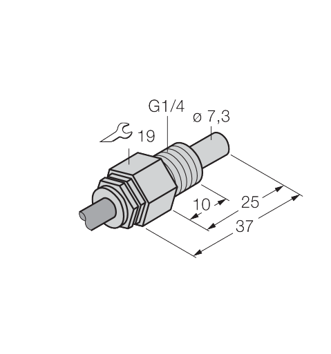
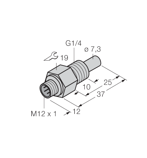 Flow Monitoring – Immersion Sensor without Integrated Processor6870341
 -
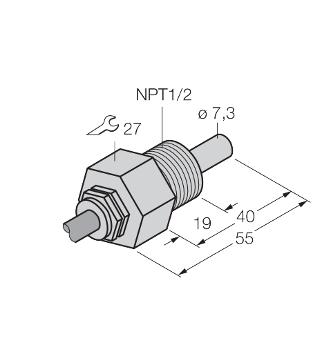
 Flow Monitoring – Immersion Sensor without Integrated Processor6870432
 -
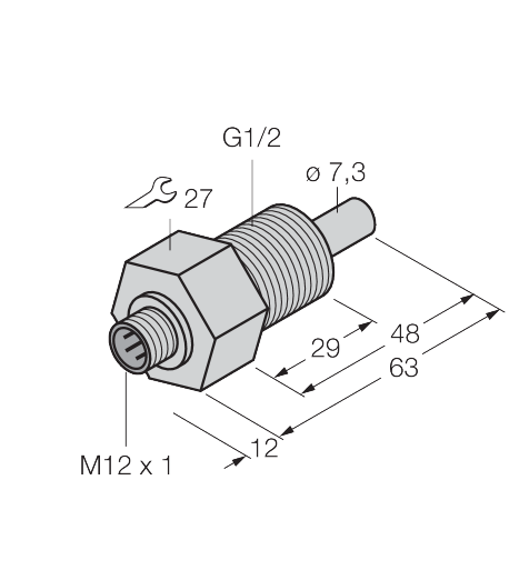
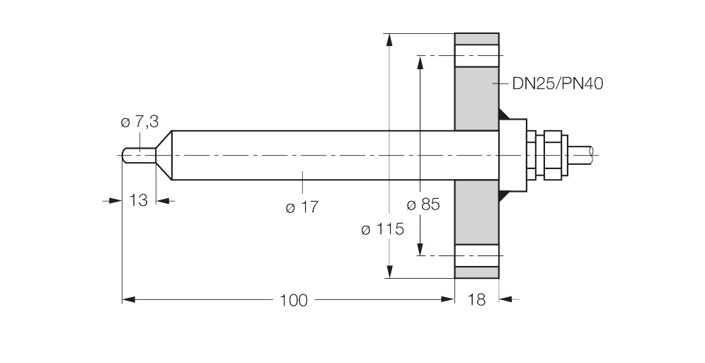
 Flow Monitoring – Immersion Sensor without Integrated Processor6870465
 -
 Flow Monitoring – Immersion Sensor without Integrated Processor6870471
 -
 Flow Monitoring – Immersion Sensor without Integrated Processor6872035