Turck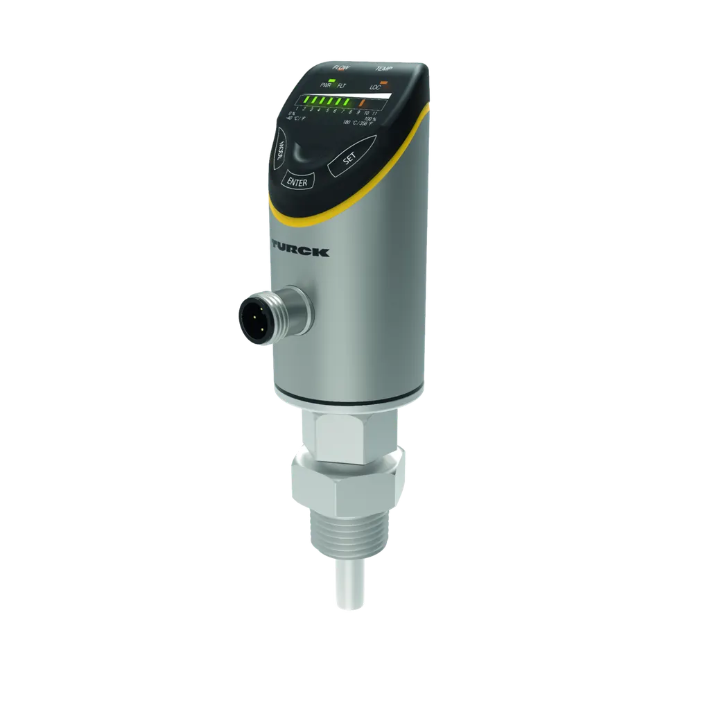
Turck
Flow Sensor
SKU: 100001007 Type: FS100-300L-16-2UPN8-H1141
Available3–5 business days delivery
€340.50 / pieces
€405.20 incl. VAT
These are our list prices.Get an individual quote within 24 h.
Request a quoteFeatures
- Screw-in adaptor with process connection NPT 1/2" male thread included in delivery
- Electronics housing material/medium contact 1.4404 (316L)/1.4571 (316Ti)
- Immersion depth 16.9 mm
- Process value display with bar graph
- Flow monitoring for liquid media
- Protection classes IP66, IP67 and IP69K
- Adjustment of flow speed via teach function
- 10…33 VDC
- NO/NC contact, PNP/NPN output, IO-Link
- Connector, M12 × 1
Functional principle
The flow sensor functions according to the calorimetric principle. The distinctive feature of this principle is that the flow rate correlates directly to the thermal loss of energy in the probe. The increased loss of energy is therefore a direct measure of an increased flow rate.
LED display
| Byte n+1 | 16 Bit Process Value (FLOW) |
| Flow | Yellow On NO: Flow switchpoint exceeded (output "high") |
| Flow | NC: Flow below minimum switchpoint (output "high") |
| Flow | Off NO: Flow below minimum switchpoint (output "low") |
| Flow | NC: Flow switchpoint exceeded (output "low") |
| Flow | Flashing Teach mode/display of diagnostic data |
| Flow | (see manual for specification) |
| Temp | Yellow On NO: Temperature switchpoint exceeded (output "high") |
| Temp | NC: Temperature below minimum switchpoint (output "high") |
| Temp | Off NO: Temperature below minimum switchpoint (output "low") |
| Temp | NC: Temperature switchpoint exceeded (output "low") |
| Temp | Flashing Teach mode/display of diagnostic data |
| Temp | (see manual for specification) |
| FLT | Red On Error displayed |
| FLT | (for error pattern in combination with LEDs see manual) |
| FLT | Off No errors displayed |
| IO-Link proc | ess data image |
| LOC | Yellow On Device locked |
| LOC | Off Device unlocked |
| LOC | Flashing Locking/unlocking process active |
| Byte n | 14 Bit Process Value (TEMP) State Out 2 (TEMP) State Out 1 (FLOW) |
| For detailed | description of the display patterns and flashing codes, see manual D10000208 |
| PWR | Green On Operating voltage applied |
| PWR | Device is operational |
| PWR | Flashing Operating voltage applied |
| PWR | IO-Link communication active |
| PWR | (inverted flash with T on 900 ms and T off 100 ms) |
| LED | Color Status Description |
| Bit | 15 14 13 12 11 10 9 8 7 6 5 4 3 2 1 0 |
| Bit | 31 30 29 28 27 26 25 24 23 22 21 20 19 18 17 16 |
Flow Monitoring
| Reproducibility +/- | 1…30 cm/s; for water 3…300 cm/s |
| Reproducibility +/- | 0.2…5 cm/s ; for water 3…100 cm/s; |
| Reproducibility +/- | 10…80 °C |
| Switching point accuracy | Directed inflow to punch mark ±20 ° |
| Temperature drift | 0.5 cm/s x 1/K |
| Standard flow range | 3…300 cm/s |
| Standard flow range | Any axial alignment of the sensor rod in |
| Standard flow range | the medium |
| Hysteresis | ≤ 300 K/min |
| Hysteresis | 3 … 25 % of the switching point |
| Extended flow range | 1…300 cm/s |
| Temperature gradient | 0.5 cm/s × 1/K |
| Response time T09 | 6 s |
Temperature monitoring
| Reproducibility +/- | ≤ 0.5 K |
| Reproducibility +/- | 12 s |
| Switching point accuracy | ± 2 K; for water >3 cm/s |
| Resolution | 0.5 K |
| Measuring range | -25…85 °C |
| Response time T09 | 3 s |
Application range
| Bar length (L1) | 45 mm |
| Pressure resistance | 300 bar |
| Immersion depth (L) | 16.9 mm, bei Verwendung des mitgelieferten Adapters |
| Application range | liquids |
| Installation conditions | Immersion sensor |
Electrical data
| Standby delay time | 18…30 s |
| Short-Circuit/Reverse Polarity Protection | yes, cyclic / yes (voltage supply) |
| Voltage drop | ≤ 1.8 VDC |
| Overload protection | Yes |
| Operating voltage | from 10 to 33 V |
| Power consumption | up to 1.6 VA |
| Electrical safety class | III |
Ambient Conditions
| Vibration resistance | 20 g (55…2000 Hz) DIN EN 60068-2-6 |
| Ambient temperature | from -40 to 80 °C |
| Storage temperature | from -40 to 80 °C |
| Shock resistance | 50 g (11 ms) DIN EN 60068-2-27 |
Tests/approvals
| MTTF | 120 years acc. to SN 29500 (Ed. 99) 40 |
| MTTF | °C |
| Indication | LED display functions for status of supply |
| Indication | voltage, switching states and teach processes. Process indicators via bar graph. |
| UL registration number | E516036 |
| Approvals | cULus |
| Approvals | CE |
IO-Link
| Transmission physics | COM 2 (38.4 kBaud) |
| IO-Link port type | Class A |
| Frame type | 2.2 |
| Included in the SIDI GSDML | Yes |
| IO-Link specification | V 1.1 |
Mechanical data
| Elektrischer Anschluss | Connector, M12 × 1 |
| Adapter material | Stainless steel 1.4571 (316Ti) |
| Process connection | 1/2'' NPT male thread |
| Materials (media-contacting) | Stainless steel 1.4571 (AISI 316Ti), FKMO-ring |
| Process connection adapter | M18 × 1.5 male thread; 1/2" NPT male |
| Process connection adapter | thread |
| Housing material | Stainless-steel/Plastic, 1.4404 (AISI |
| Housing material | 316L)/Grilamid TR90 UV/Elastollan C 65 |
| Housing material | A 15 HPM 000/Ultramid A3X2G5 |
| Electromagnetic compatibility (EMC) | DIN EN 60947-5-9: 2007 |
| Process connection sensor | M18 x 1.5 female thread |
| Degree of protection (IP) | IP67 |
| Degree of protection (IP) | IP66 |
| Degree of protection (IP) | IP69K |
Output
| Output function | NO/NC programmable, PNP/NPN |
| Output 1 | Flow: Switching output or IO-Link |
| Output 2 | Temperature: Switching output |
| Communication protocol | IO-Link |
Allgemein
| Medium temperature | from -25 to 85 °C |
Programming
| Programming options | Automatic switching logic recognition, |
| Programming options | easy switching pointadjustment via touchpads |
Other
| Process connection | NPT 1/2 Außengewinde |
| Housing material | Edelstahl |
| Housing material | Kunststoff |
| Connector type | M12 |
| Switching output | Schließer/Öffner |
| Switching output | PNP |
| Switching output | NPN |
 Accessories Screw-In Adapter For Immersion Flow Sensors FS/FP100001987
 Accessories Screw-In Adapter For Immersion Flow Sensors FS/FP100001989
- Accessories Screw-In Adapter For Immersion Flow Sensors FS/FP100001988
 Accessories Screw-In Adapter For Immersion Flow Sensors FS/FP100001990
- Screw-in adapter for immersion sensors from the series FS.. , FP..; material: Stainless steel 1.4571 (316Ti); process connection: G3/4"100001991