Turck 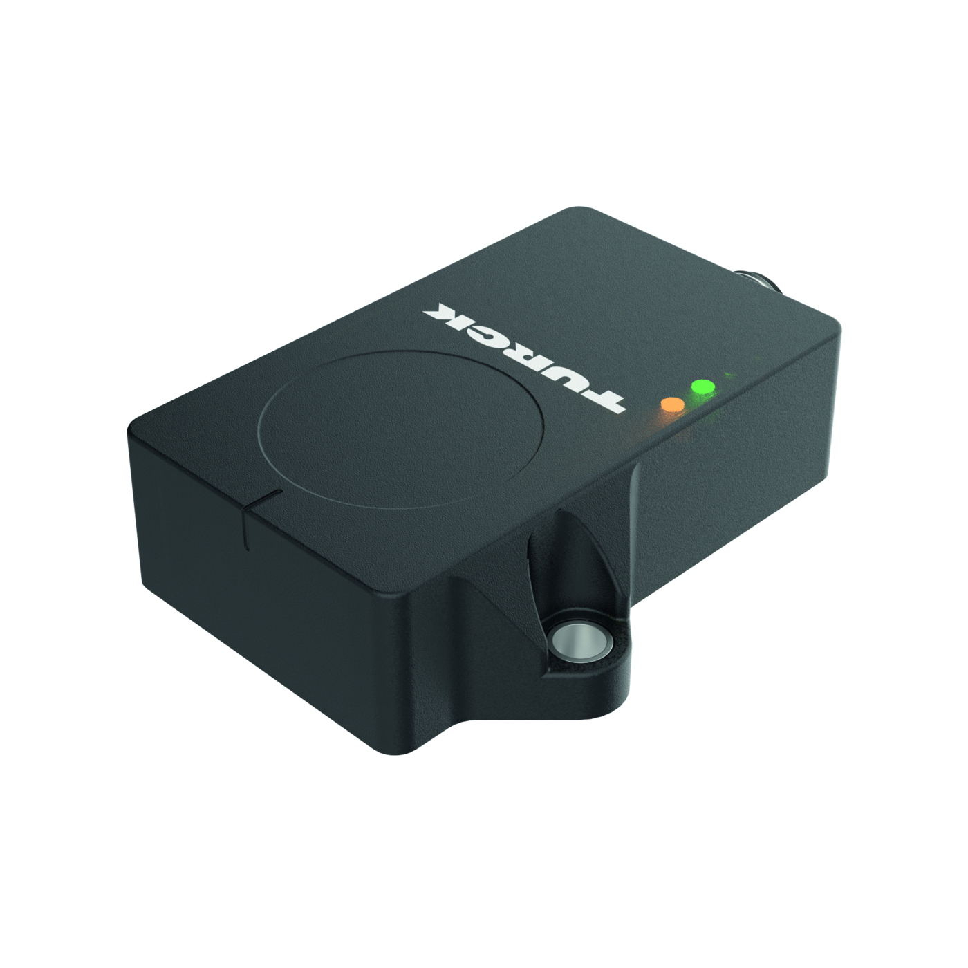
Turck
Dynamic Inclinometer With Analog Outputs
SKU: 100030754 Type: B1NF360V-QR20-2LI2X3-H1151
Available 3–5 business days delivery
€345.00 / pieces
€410.55 incl. VAT
Features
- • Rectangular, plastic, Ultem
- • Status displayed via LED
- • Angle detection via one axis with 360 ° measuring range
- • High protection class IP68/IP69K
- • Protected against salt spray and rapid temperature change
- • 15…30 VDC
- • M12 × 1 male connector, 5-pin
- • Two counter-running 4…20 mA analog outputs improve machine safety through redundancy
- • The start, end and center point of the measuring range can be adjusted using teach adaptor TX1-Q20L60
- • Individual parameterization possible with USB-2-IOL-0002
Functional principle
The dynamic inclinometers use an acceleration measuring cell and a gyroscope sensor to determine angles. Influences caused by vibrations or interfering acceleration are minimized by applying an intelligent fusion algorithm to the acceleration data and the rotation rate values. This enables the sensor to output a robust signal with impressive precision and speed, even in moving, dynamic applications. The robust sensors are positioned with the cast side on a flat surface so that the casting compound is covered. The sensor is then secured with two screws.
Ambient Conditions
| Activate sequence* | Set bridge for 2…8 s After 2 s of flashing at 1 Hz |
| Activate teaching | Before switching on the supply Teach process active: |
| Activate teaching | voltage, set the teach bridge, 700 ms/100 ms |
| Activate teaching | then switch on the voltage, |
| Activate teaching | then remove the bridge immediately after starting the sensor |
| Display operating voltage | LED, Green |
| The teach process is automatic to normal operation. | ally deactivated after 30 s. The yellow CENTER LED and the green LED flash alternately and then return |
| Teach sequence for center po | int, measuring range start and end |
| Teach sequence for center po | Bridge between pin 5 and pinLED green LED yellow |
| Teach sequence for center po | 1 |
| MTTF | 297 years acc. to SN 29500 (Ed. 99) 40 °C |
| Set end of measuring range** | Bridge for 14…20 s After 14 s of flashing at 4 Hz |
| Ambient temperature | from -40 to 85 °C |
| Temperature changes (EN60068-2-14) | -40… +85 °C; 20 cycles |
| Measuring range display | LED, yellow |
| UL Certificate | E351232 |
| UL Certificate | Bridge between pin 5 and pinLED green LED yellow |
| UL Certificate | 1 |
| Set start of measuring range** | Bridge for 8…14 s After 8 s of flashing at 2 Hz |
| Vibration resistance | 20 g; 5 h/Achse; 3 |
| Set center point** | Bridge for 2…8 s After 2 s of flashing at 1 Hz |
| Shock resistance | 200 g; 4 ms ½ sine |
| Degree of protection (IP) | IP69K |
| Degree of protection (IP) | IP68 |
Electrical data
| Wire break/reverse polarity protection | yes/yes |
| Isolation test voltage | 0.5 kV |
| Load resistance voltage output | ≥ 4.7 kΩ |
| Current output | 4…20 mA |
| Electricity consumption | up to 80 mA |
| Short circuit protection | yes |
| Output function | 5-pin, Analog output |
| Load resistance current output | ≤ 0.4 kΩ |
| Ripple Uss | ≤ 10 % UBmax |
| Operating voltage UB | from 15 to 30 VDC |
General data
| Number of measurement axes | 1 |
| Temperature drift | ≤ ± 0.006 %/K |
| Resolution | 16 bit |
| Repeatability | ≤ 0.03 % of full scale |
| Measuring range | 0…360° |
| Linearity deviation | ≤ 0.15 % |
Factory setting
| Activate sequence for factory settings* | Bridge for 8…14 s After 2 s of flashing at 2 Hz |
| Reset to factory settings** | Bridge for 2…8 s After 2 s of flashing at 1 Hz |
Mechanical data
| Elektrischer Anschluss | Connector, M12 × 1 |
| Design | Rectangular, QR20 |
| Housing material | Plastic, Ultem |
| Abmessung | 71.6 x 62.6 x 20 mm |
Allgemein
| Measurement principle | Combination of gyroscopes and accelerometers |