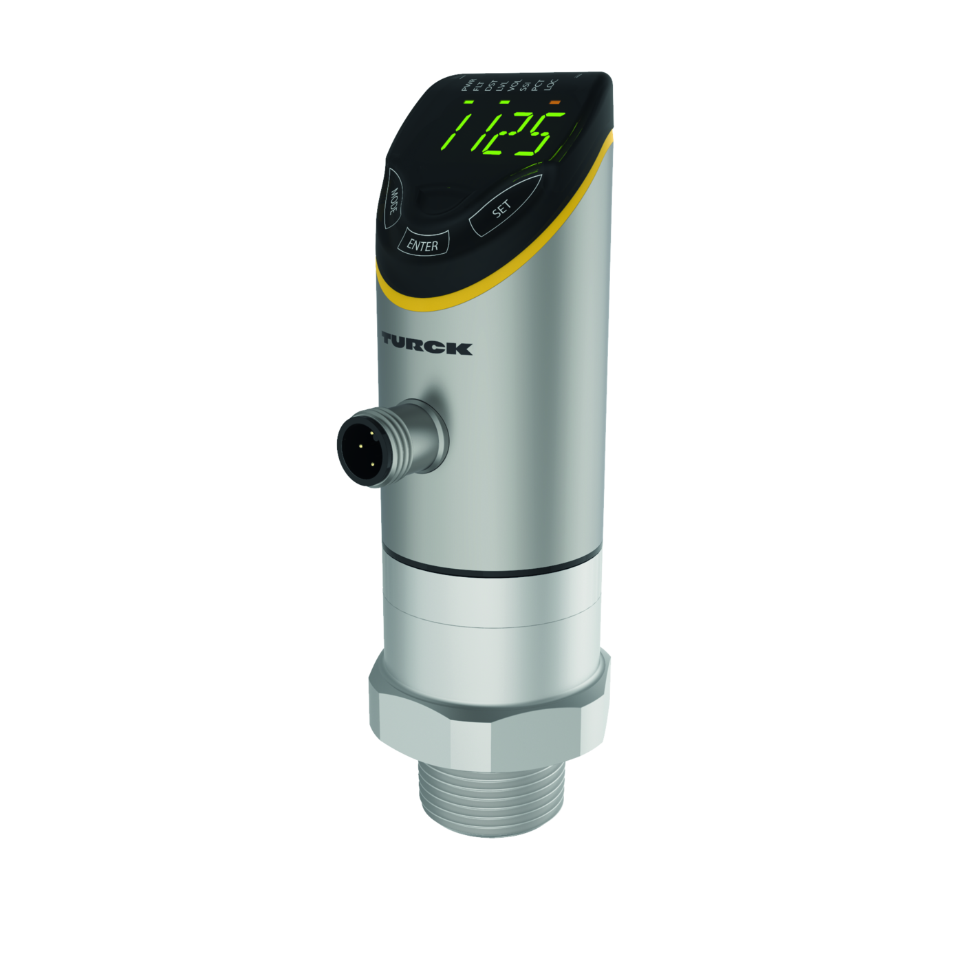
Radar Sensor – Level Control
Features
- • Range: 10 m
- • Blind zone: 35 cm
- • Resolution: 1 mm
- • Cone angle of the radar beam: ±5°
- • Distance, level, volume or % output
- • Approved according to ETSI 305550-2
- • Approved according to FCC/CFR. 47 Part 15.
- • Male connector, M12 × 1, 4-pin
- • Operating voltage 18…33 VDC
- • Switching output switchable between PNP/ NPN
- • IO-Link
- • 4-digit, 2-colored, 14-segment display
- • Housing is rotatable by 180° after mounting the process connection
- • Process connection NPT 3/4"
- • Pressure resistance -1…16 bar rel.
Functional principle
FMCW radar stands for frequency modulated continuous wave radar. FMCW is the English abbreviation for Frequency Modulated Continuous Wave. Non-modulated continuous wave radars have the disadvantage that they cannot measure distances due to lack of time reference. Such a time reference for distance measurement of stationary objects can be generated by means of frequency modulation. Using this method, a signal is emitted which continually changes the frequency. A periodic, linear frequency which varies upwards and downwards is used to limit the frequency range and to simplify the signal evaluation. The factor for the rate of change df/dt remains constant. If an echo signal is received, then this has a runtime delay as with the pulse radar, and thus a different frequency that is proportional to the distance.
Electrical data
| DC rated operating current Ie | ≤ 250 mA |
| Response time typical | < 10 ms |
| Switching frequency | up to 10 Hz |
| Voltage drop at Ie | ≤ 2 V |
| Short circuit protection | yes/Cyclic |
| Polarity protection | yes |
| Output function | NO/NC programmable, PNP/NPN |
| Output 2 | Switching output |
| Communication protocol | IO-Link |
| Residual ripple | < 10 % Uss |
| No-load current | up to 100 mA |
| Residual current | ≤ 0.1 mA |
| Operating voltage UB | from 17 to 33 VDC |
Mechanical data
| Display switch state | 2 × LEDs, Yellow |
| EMC | EN 61000-6-2:2019 |
| EMC | ETSI EN 301489-3 v.1.6.1 |
| Vibration resistance | 20 g (10…2000Hz), |
| Elektrischer Anschluss | Connector, M12 × 1 |
| Pressure resistance | 16 bar |
| Lens | plastic, PEEK |
| Ambient temperature | from -25 to 65 °C |
| Shock test | EN 60068-2-27 |
| Process connection | 3/4'' NPT |
| Approvals | cULus |
| Approvals | CE |
| Approvals | FCC |
| Approvals | ETSI |
| Storage temperature | from -40 to 85 °C |
| Design | With display (integrated probe), LRS |
| Max. tightening torque of housing nut | 45 Nm |
| Housing material | Stainless-steel/Plastic, 1.4404 (AISI |
| Housing material | 316L)/polyarylamide 50 % GF UL 94 V-0 |
| Housing material | PEEK |
| Shock resistance | 50 g (11 ms) |
| Degree of protection (IP) | IP67 |
| Degree of protection (IP) | IP69K |
| Abmessung | Ø 38 x 132.3 x 38 x 50.2 mm |
IO-Link
| Maximum Cable Length | 20 m |
| IO-Link port type | Class A |
| Communication mode | COM 3 (230.4 kBaud) |
| Function pin 4 | IO-Link |
| Function Pin 2 | DI |
| Frame type | 2.2 |
| Process data width | 80 bit |
| Minimum cycle time | 5 ms |
| Profile support | Smart Sensor Profile |
| Switchpoint information | 2 bit |
| IO-Link specification | V 1.1 |
| Measured value information | 64 bit |
Radar data
| Edge lengths of the nominal actuator | 100 mm |
| Function | Radar scanner |
| Resolution | 1 mm |
| Range | from 0.35 to 10 m |
| Hysteresis | ≤ 50 mm |
| Minimum switching range | 50 mm |
| Linearity error | ≤ ± 0.1 % |
| Opening angle | 10 ° |
| Repeatability | 2 mm |
| Frequency range | from 122000000000 to 123000000000 Hz |
| Minimum measuring range | 500 mm |
| Output power EIRP | 10 dBm |
- Actuator and Sensor Cable, PVC – Connection Cable6625025
-
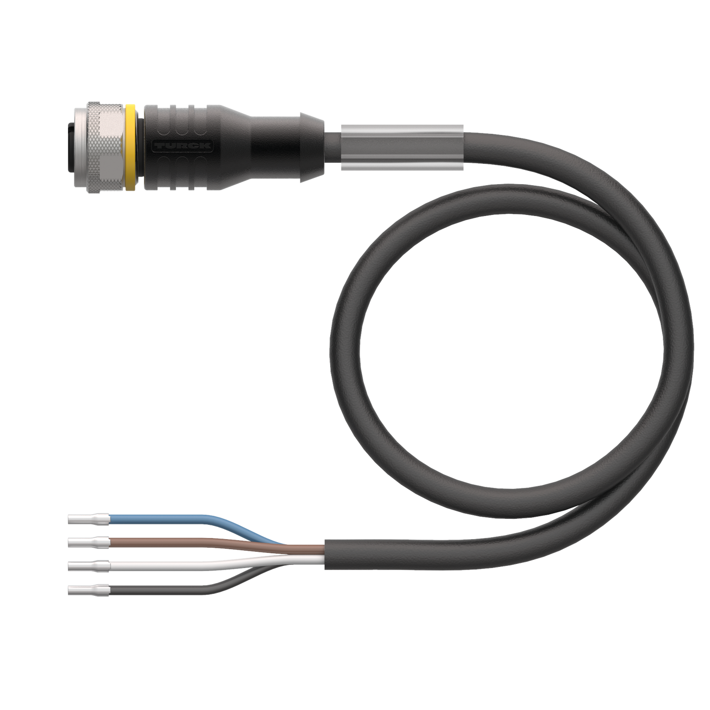 Actuator and Sensor Cable, PVC – Connection Cable6625013
 -
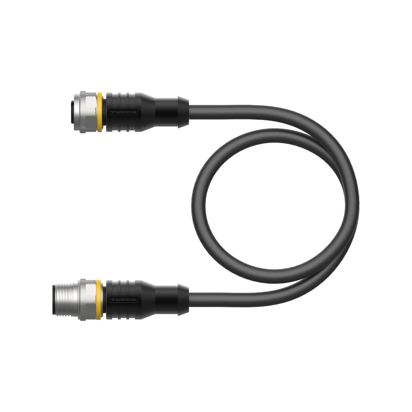 Actuator and Sensor Cable, PVC – Extension Cable6625208