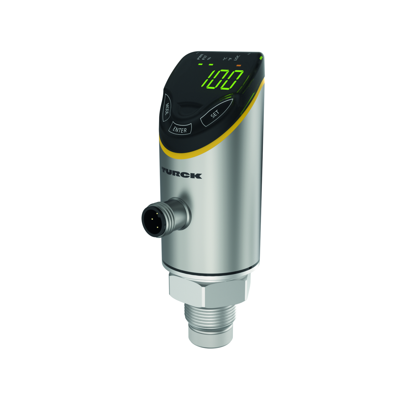
Flow Monitoring Processor Unit – With 2 PNP/NPN Transistor Switching Outputs
Features
- • Sensor housing material 1.4404 (316L)
- • Media-contacting material: sensor dependent
- • 4-digit, 2-color (red/green), 12-segment display, rotatable by 180°
- • Protection class IP66, IP67 and IP69K (connected with sensor/sensor cable)
- • Adjustment of flow rate via teach function
- • 17…33 VDC
- • NO/NC contact, PNP/NPN output, IO-Link
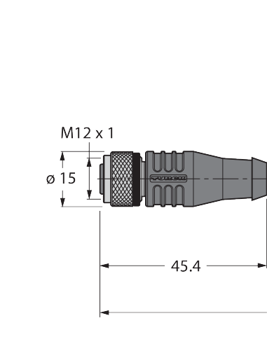
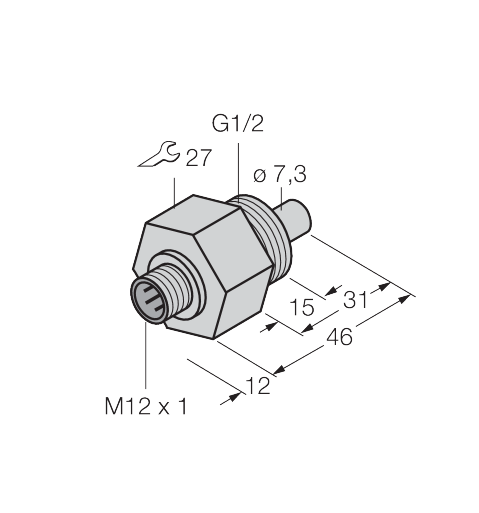
- • M12 × 1 connector
- • IO-Link with Smart Sensor Profile SSP4.1.2
Functional principle
All non-Ex flow sensors from the FP100, FCS-… (immersion sensors) and FCI (inline sensors) series can be operated with the FS121-… external signal processor. The signal processor features 4 status LEDs and a 12-segment display for local visual monitoring. Software-based diagnostic options are also available to the user, including detection of sensor-side wire breaks and short circuits, as well as monitoring of the operating and display range for the flow rate and media temperature. The upper and lower limits of the flow range are taught in using the max./min. teach mode implemented. The flow switching point can be optionally adjusted by means of the QuickTeach function, without having to teach in the lower and upper limits of the flow range. Working on the calorimetric principle, the connectible sensors not only detect the flow rate but also the media temperature. The flow module can be operated either in IO-Link (IOL) or in standard IO (SIO) mode via the integrated IO-Link interface. In SIO mode, the switching outputs are operated in the standard way. In IOL mode, the current process values are transmitted cyclically in series as digital 32-bit values. Parametrization can be performed either via touch button or using software via the IO-Link communication interface. The parameterization via IO-Link is performed
Flow Monitoring
| Reproducibility +/- | Typically <3 % (depending on the probe |
| Reproducibility +/- | connected and the measuring range) |
| Switching point accuracy | Typically <5 % (depending on the probe |
| Switching point accuracy | connected and the measuring range) |
| Hysteresis | 5…20 % (depending on the detection |
| Hysteresis | range) |
| Ansprechzeit (bei ruhender Luft) | Dependent on the probe connected |
Temperature monitoring
| Reproducibility +/- | Typically ≤ 0.5 K (depending on the probe |
| Reproducibility +/- | connected) |
| Switching point accuracy | Typically ± 2 K (depending on the probe |
| Switching point accuracy | connected) |
| Resolution | 0.1 K |
Displays/Operating elements
| Display switch state | 2 × LEDs, Yellow |
| MTTF | 120 years acc. to SN 29500 (Ed. 99) 40 |
| MTTF | °C |
| Indication | 4-digit 12-segment display, rotatable by |
| Indication | 180°, red or green |
IO-Link
| Maximum Cable Length | 20 m |
| Transmission rate | COM 2 (38.4 kBaud) |
| IO-Link port type | Class A |
| Function pin 4 | IO-Link |
| Function Pin 2 | DI |
| Frame type | 2.2 |
| Process data width | 64 bit (2 × 32 bit, of which 2 × 6 bit are |
| Process data width | not used) |
| Minimum cycle time | 6 ms |
| Profile support | Smart Sensor Profile (SSP4.1.2) |
| Included in the SIDI GSDML | In preparation |
| Switchpoint information | 4 bit (2 × 2 switching points) |
| IO-Link specification | V 1.1 |
| Measured value information | 48 bit (2 × (16-bit process values + 8-bit |
| Measured value information | scale)) |
Electrical data
| Standby delay time | 30 s |
| Short-Circuit/Reverse Polarity Protection | yes, cyclic / yes (voltage supply) |
| Voltage drop | ≤ 2 VDC |
| Protective measure | SELV, PELV according to DIN EN 61140 |
| Overload protection | Yes |
| Operating voltage UB | from 17 to 33 VDC |
| Power consumption | up to 3 VA |
| Electrical safety class | III |
Ambient Conditions
| Vibration resistance | 20 g DIN EN 60068- |
| Ambient temperature | from -40 to 80 °C |
| Storage temperature | from -40 to 80 °C |
| Shock resistance | 50 g (11 ms) DIN EN 60068-2-27 |
Mechanical data
| Elektrischer Anschluss | Connector, M12 × 1 |
| Housing material | Stainless-steel/Plastic, 1.4404 (AISI |
| Housing material | 316L)/Grilamid TR90 UV/Elastollan C 65 |
| Housing material | A 15 HPM 000/Ultramid A3X2G5 |
| Electromagnetic compatibility (EMC) | DIN EN 60947-5-9: 2007 |
| Degree of protection (IP) | IP67 |
| Degree of protection (IP) | IP66 |
| Degree of protection (IP) | IP69K |
Allgemein
| Remark to product | Some examples of flow sensors that can |
| Remark to product | be connected can be found under "Functional accessories" at the end of this data |
| Remark to product | sheet. |
| Installation conditions | Connection of Turck flow sensors, max. |
| Installation conditions | cable length 30 m. Recommendation: |
| Installation conditions | shielded cable |
Tests/approvals
| UL registration number | E516036 |
| Approvals | cULus |
Output
| Output function | NO/NC programmable, PNP/NPN |
| Output 1 | Flow: Switching output or IO-Link |
| Output 2 | Temperature: Switching output |
| Communication protocol | IO-Link |
Programming
| Programming options | Switching behavior (PNP/NPN/Auto); |
| Programming options | switching logic (high/low); switching point |
| Programming options | set via touchpads: single point, two point, |
| Programming options | window mode; display: color: red/green |
| Programming options | including color change when switching, |
| Programming options | display orientation 0°/180°, update time, |
| Programming options | temperature unit, password protection |
-
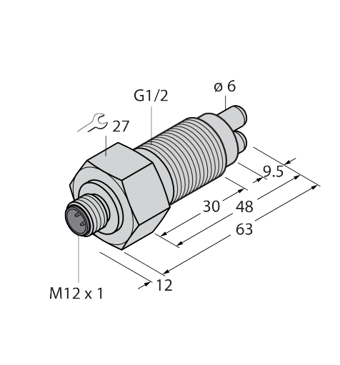
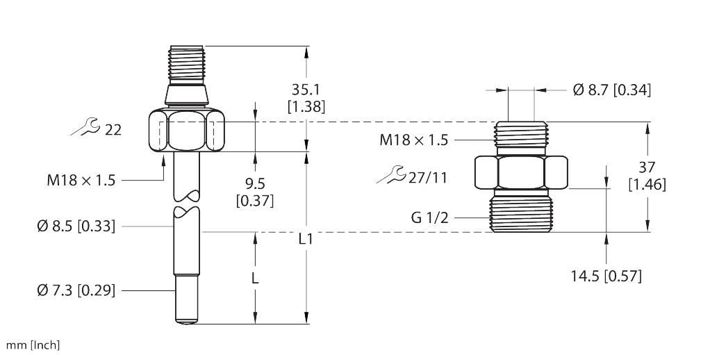 Flow Meter – Immersion Sensor without Integrated Processing Unit100001044
 -
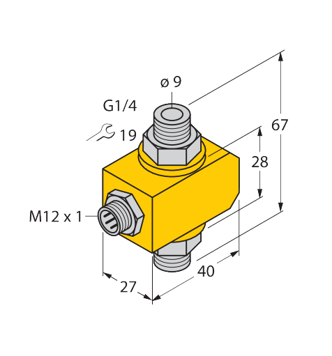
 Flow Monitoring – Functionality Corresponding to Flow Module Remote Probe6870266
 - Flow sensor for liquids — immersion sensor without integrated signal processor6870301
-
 Flow Monitoring – Immersion Sensor without Integrated Processor6870303
 - 68713106871310
-
 Flow Monitoring – Immersion Sensor without Integrated Processor6870404
 -
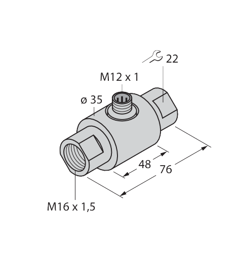
 Flow Monitoring – Inline Sensor without Integrated Processor6870629
 -
 Flow Monitoring – Inline Sensor without Integrated Processor6870631