Turck 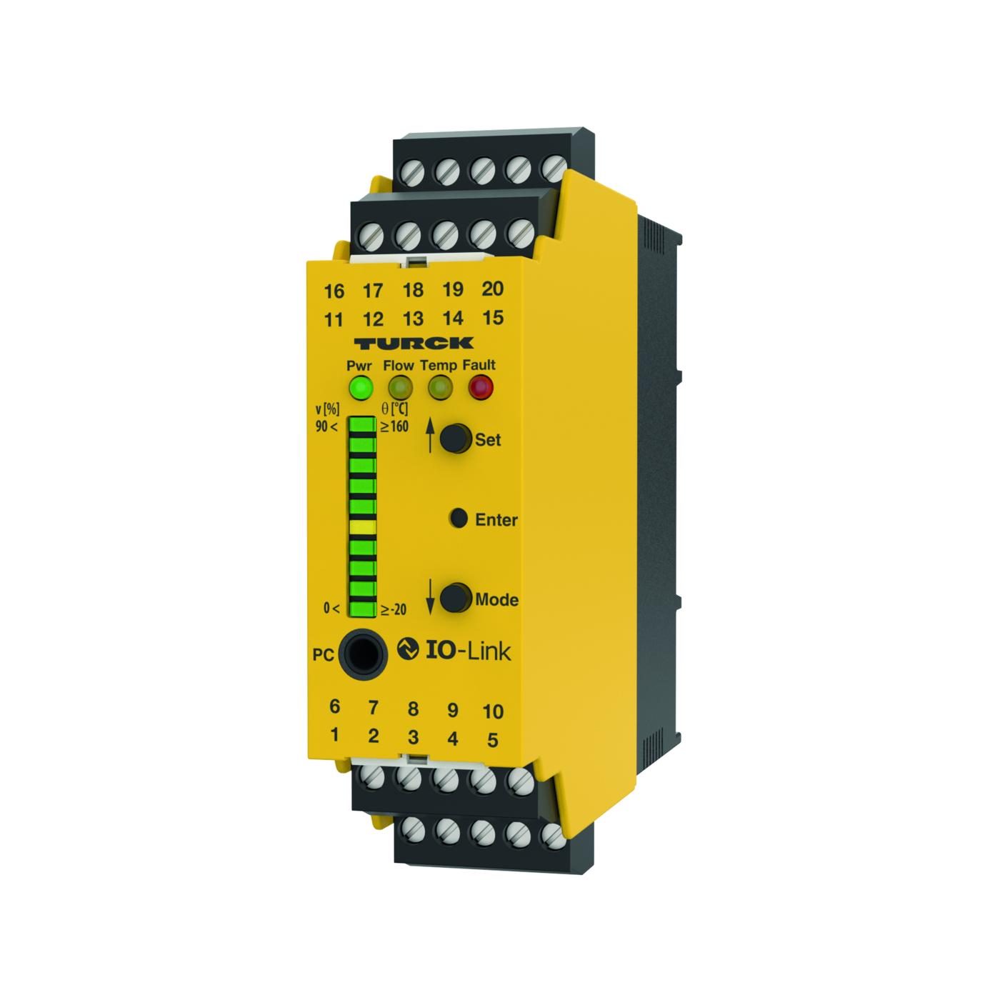
Turck
Processor Unit – For the Connection of FCS and FCI Product Series Flow Sensors IO-Link Device with Transistor Switching Outputs
SKU: 7525100 Type: FM-IM-3UP63X
Available 3–5 business days delivery
€279.10 / pieces
€332.13 incl. VAT
Features
- • Transistor outputs for flow, temperature and faults
- • Adjustment of switchpoint, no teaching of flow boundaries (QuickTeach)
- • LED band for indication of flow speed and media temperature
- • Monitoring of operating and display range
- • Detection of wire-break and short-circuit on the sensor side
- • Standard IO or IO-Link operating mode
- • Parametrized via pushbutton or software-supported via IO-Link
Functional principle
All non-Ex flow sensors from the FCS series (immersion sensors) and FCI series (inline series) can be operated with the FM-IM external processing unit. The flow module features four status LEDs the standard way. In IOL mode the current process signal is transmitted cyclically as a 10 bit-serial value. Parametrization is initiated either via pushbutton or software-supported via IOLink interface. The actual parametrization is then implemented via the tool-based DTM or IODD within the FDT frame PACTware™ or acyclically near the control via On-Request Data Objects (ORDO).
Mechanical data
| Flow | yellow off Switching output flow [low] |
| Flow | on Switching output flow [high] |
| Flow | flashing Teach mode / display of diagnostic data |
| Flow | for specification see manual |
| Flow | Value 10 Bit (Bit 15 = MSB, Bit 6 = LSB) not assigned Out 3 Out 2 Out1 |
| Flow | (Fault) (Temp) (Flow) |
| Temp | yellow off Switching output media temperature [low] |
| Temp | on Switching output media temperature [high] |
| Temp | flashing Teach mode / display of diagnostic data |
| Temp | for specification see manual |
| MTBF | 109 Years |
| Mounting method | DIN rail mounting and mounting panel |
| Bit 15 | 14 13 12 11 10 9 8 7 6 5 4 3 2 1 0 |
| Ambient temperature | from -25 to 70 °C |
| Design | Signal processor |
| PWR | green on Operating voltage applied |
| PWR | Device ready for operation |
| PWR | flashing Operating voltage applied |
| PWR | IO-Link communication active |
| PWR | (inverted flash with T on 900 ms and T off 100 ms) |
| LED displa | y |
| LED | Color Status Description |
| Housing material | Plastic, Polycarbonate/ABS |
| Fault | Red Off Switching output fault [high] |
| Fault | On Switching output flow [low] |
| Fault | (for error pattern in combination with LEDs see manual) |
| For detaile IM/FMX-IM IO-Link (Pr | d description of the display patterns and flashing codes see instructi |
| For detaile IM/FMX-IM IO-Link (Pr | ocess Data Objects) |
| Degree of protection (IP) | IP20 |
| Abmessung | 89 x 110 x 27 mm |
Customizable output functions
| Display switch state | active high / active low parametrizable |
| Display switch state | (transistor output error monitoring only |
| Display switch state | active low) |
| Switching characteristic | PNP |
| Error monitoring | transistor output |
| Flow Monitoring | transistor output |
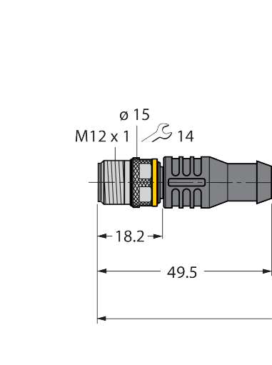
| Electrical connections | 5-pole removable reverse polarity protected terminal blocks |
| Type of fastening | screw connection |
| Temperature monitoring | transistor output |
| Switching current | 100 mA |
| Terminal cross-section | ≥ 1.5…≤ 2.5 mm² |
| Switching voltage | from 20 to 30 V |
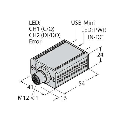
IO-Link
| Transmission rate | 38.4 kBit/s (COM 2) |
| Communication modes | Tool based engineering via FDT / DTM, |
| Communication modes | IODD. Acyclic communication via On-Request Data Objects |
| Included in the SIDI GSDML | Yes |
| Communication channel | Clamp 12 and via front panel jack COM |
| Communication channel | (PC) |
| IO-Link specification | V 1.0 |
Electrical data
| Measurement frequency | 5 Hz (every 200 ms with software filter) |
| Sensor current limitation | approx. 110 mA |
| Repeatability media temperature | typical ± 1 K |
| Medium temperature | [°C] with the SET button temporarily |
| Medium temperature | pressed |
| Measuring accuracy media temperature | typical ± 7 K |
| Sensor current | ≤ 35 mA |
| Sensor voltage | ≤ 15 VDC |
| No-load current I0 | ≤ 63 mA |
| Teach modes | QuickTeach; min/max adjustment. Teach |
| Teach modes | modes incl. DeltaFlow monitoring (teach |
| Teach modes | modes are automatically released with |
| Teach modes | the change of flow speed). |
| Input function | Connection of flow sensors (non-Ex sensors of the FCS/FCI product series only!) |
| Flow speed | [%] after min/max adjustment (permanent) |
| Flow speed | % after Quick-Teach (permanent) |
| Switchpoint hysteresis media temperature | 2 K |
| Repeatability flow rate | typical ± 1 % (of full scale) |
| Operating voltage UB | from 20 to 30 VDC |
| Power consumption | up to 4.5 VA |
Tests/approvals
| Relative humidity | EN 60068-2-38 |
| Approvals | CE |
| Approvals | C-UL U.S. submitted |
| Electromagnetic compatibility (EMC) | Acc. to NE21 |
ausgangsfunktionen
| Switching current | 100 mA |
| Switching voltage | from 20 to 30 V |
-
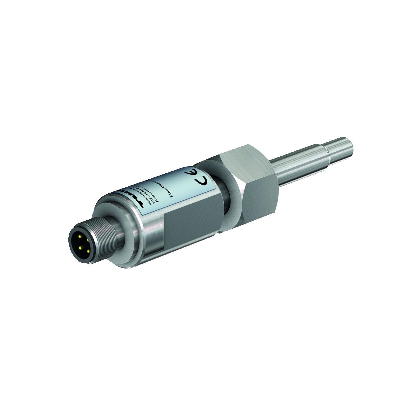 Flow Monitoring – Functionality Corresponding to Flow Module Remote Probe6870266
 -
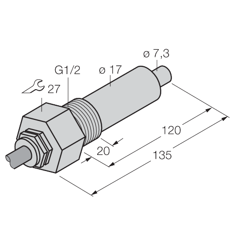 Flow Monitoring – Immersion Sensor without Integrated Processor6870359
 -
 Flow Monitoring6870638
 - Flow sensor for liquids — immersion sensor without integrated signal processor6870309
- FCS-GL1/2T-NA6870426